by Dan Talbot | Mar 21, 2019 | Projects
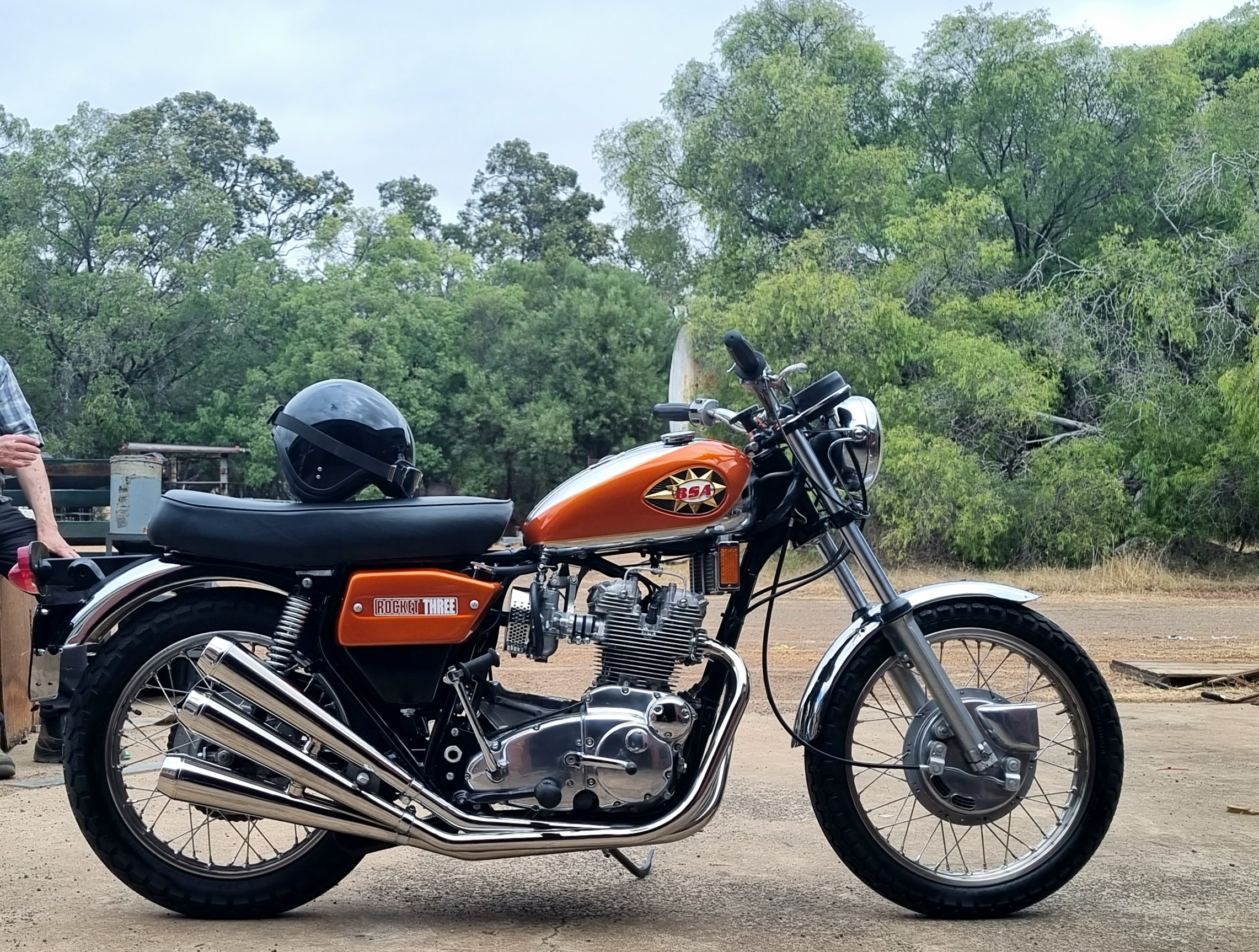
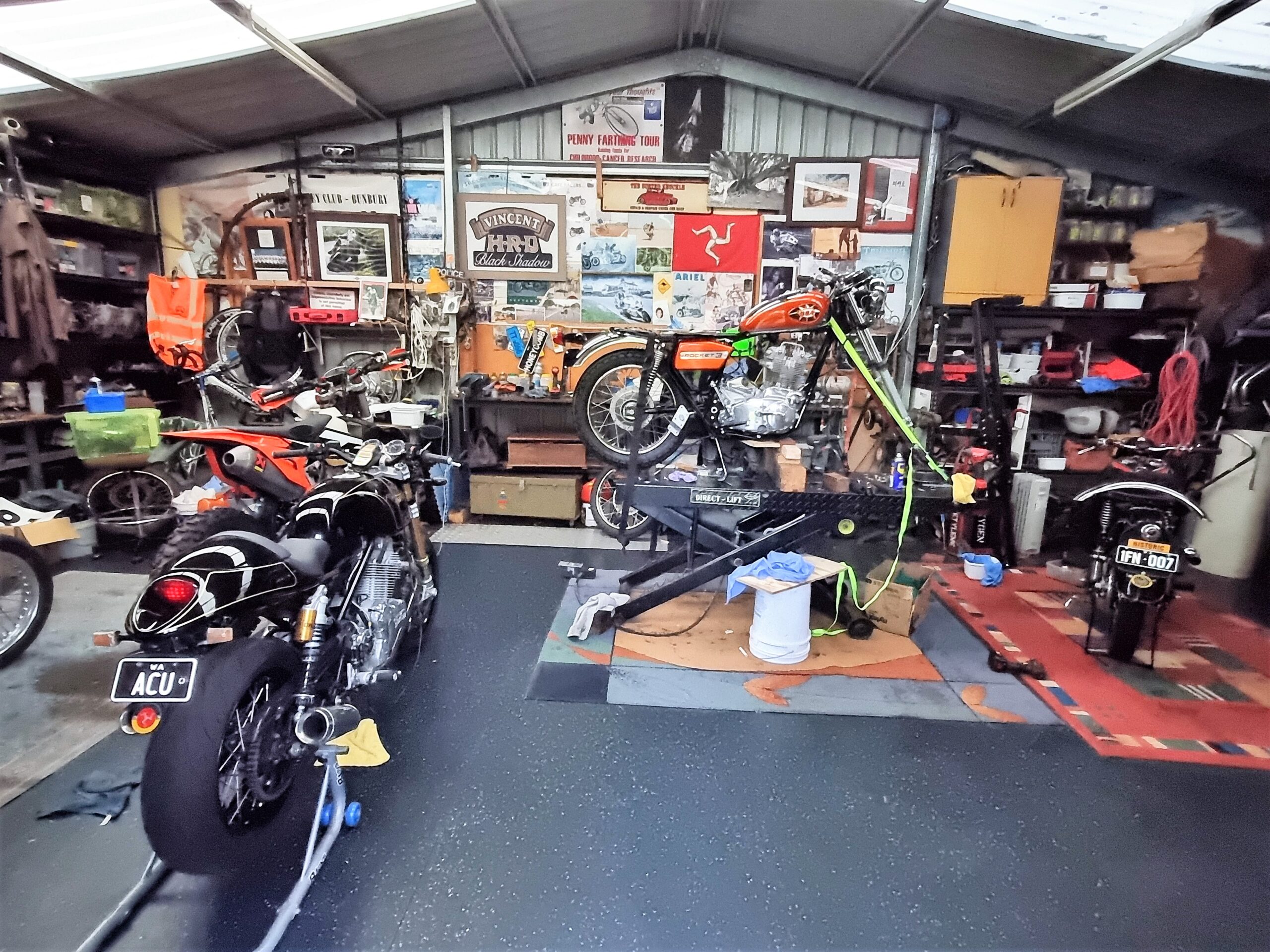
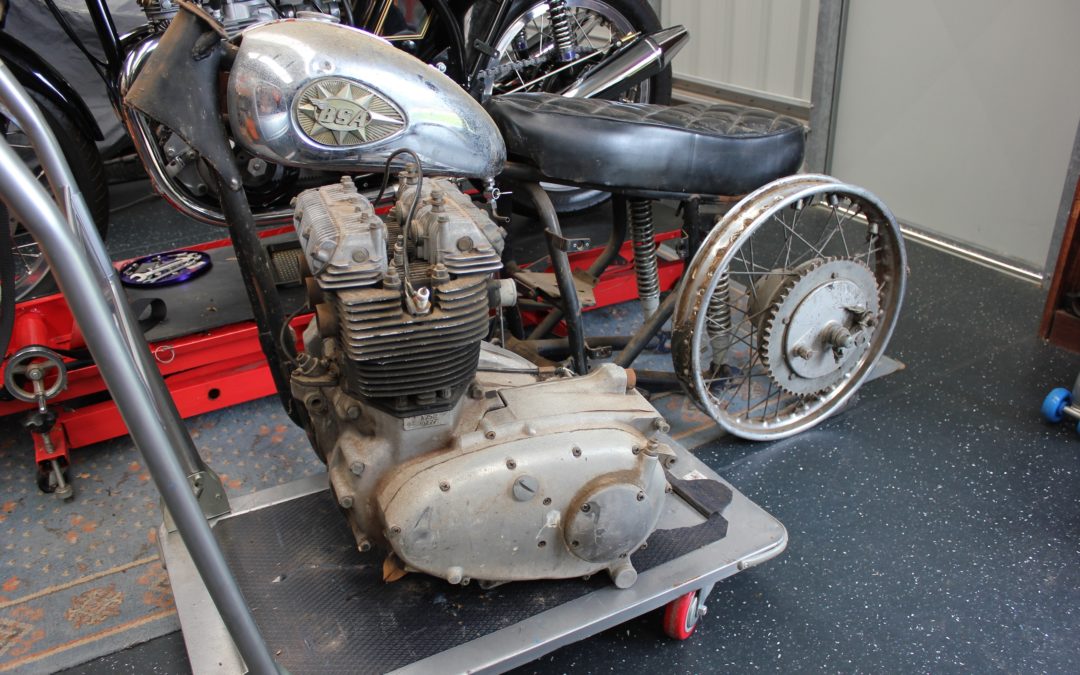
1971 BSA Rocket 3
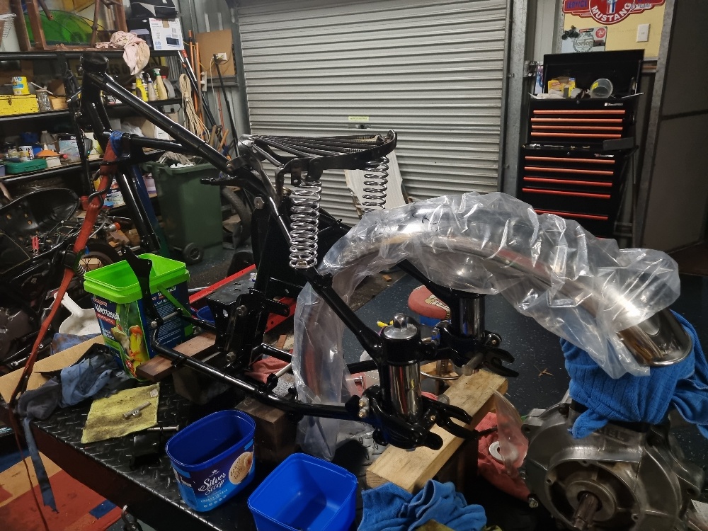
Things are moving slowly forward with the Rocket rebuild. Since we last discussed this project I’ve received a few bits and pieces back and suffered a bit of a shock where I was least expecting it. Let’s look and the shiny new bits first.
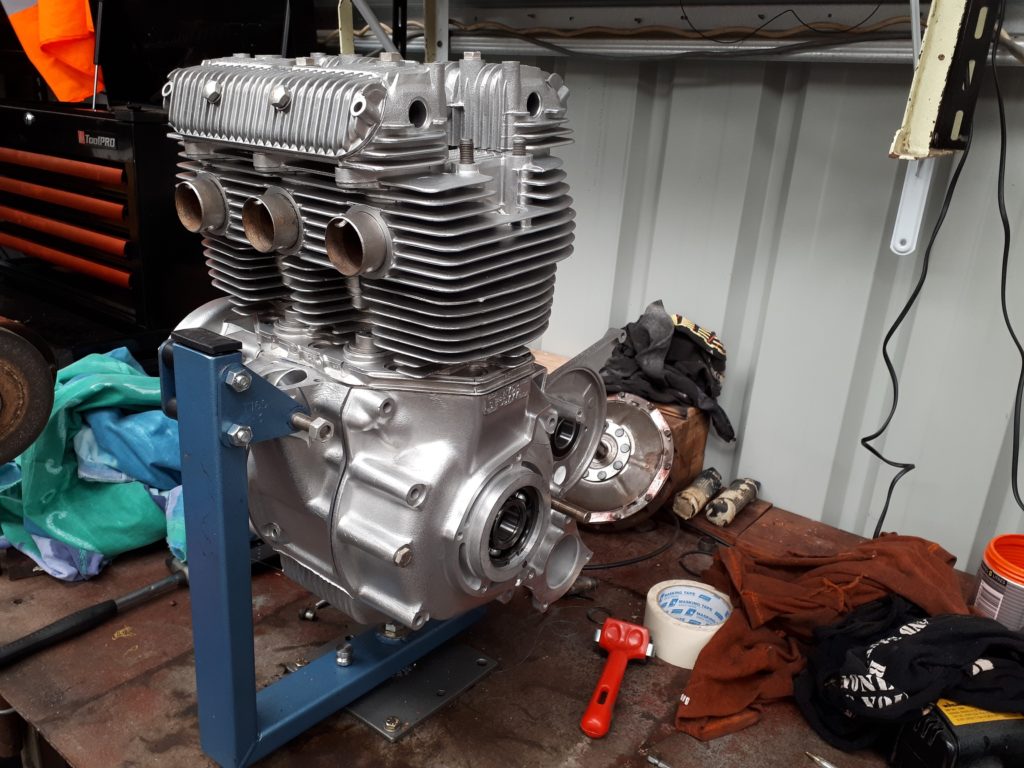
Having reduced the motorcycle to indivisible parts, the crank cases were the first items that came in for treatment and went off to Perth for a vapour blast and other tasks that needed to be done ahead of re-assembly. The main bearings were fitted and the lower oil-way return was enlarged to the later model, T160 specs, which is a common modification on the T150 engines and, of course, A75 engines of the same vintage. The result is a thing of beauty and was proudly mounted on the engine stand, befitting a masterpiece in the Guggenheim museum, as soon as I got home. I can’t bear the idea of marking them so the cases spend most of the time under cover.
Fresh from vapour blasting, the cases look as good as new – better even.
At the time of taking the remaining engine alloy pieces to Perth, my usual source in Malaga was closed so I opted for another fellow who does vapour blasting in Morley and comes highly recommended. Dropping all these items off, and knowing there’s still more at home, it becomes immediately apparent just how many alloy castings make up the BSA/Trident engine. The items left at home are pieces that I will be polishing on my buffing wheel so there’s no need to waste money having them vapour blasted first.
At this point it is worth mentioning vapour blasting is not just water, it’s more of a slurry with a super-fine medium. The result is a sparkling surface that doesn’t mark easily when touched with grubby fingers. The reason for this is the medium that is used. Sand and soda will leave alloy rough and porous, whereas vapour tends to knock out the rough leaving the surface less susceptible to staining, apparently. We’ll see.
There is significant sludge left in the journals and threads that will need to be thoroughly cleaned out before the engine goes back together but, for now, I’m content to just ogle my beautiful new engine cases without spilling sludge down the sides of it.
Fit for display in the Guggenheim.
When I purchased the engine I was told it had been re-bored at some earlier time and not run since. ‘Bewdy,’ I thought, ‘that’ll save a few bob!’ Sure enough, when I lifted the head I was treated to shiny new pistons staring back at me. True to the description the engine had indeed been re-bored to .020” oversize (evidently they don’t do .010” increments). Great, new pistons, new valves, new bore, huge savings.
The engine was apparently re-bored in the US a long time ago. By my best estimates the top end was done at least 10, possibly even 15 years ago, put back together and then shoved off into a corner to be forgotten about until my mate purchased the bike and brought it to Australia – where it was pushed it off into a corner and forgotten about.
I wanted to make sure the rings were alright so took the barrel, pistons and rings to Ben, aka the British Bike Brains Trust. Ben cast an appraising eye over the bore and simply said “that’ll need to be redone.” My guts sank a little, and maybe a tiny bit of bile started to make is way upwards. Okay, that’s an over re-action but I wasn’t expecting it. The problem being, because the engine sat for so long with the pistons in fixed positions, the bore was slightly rusty at the points where the rings were resting, resulting in an achilles heel that would flog out quickly and necessitate a re-bore at a future, more inconvenient time.
I handed them over to Ben with the instruction to do what’s necessary to ensure reliability and longevity once the Rocket is back together.
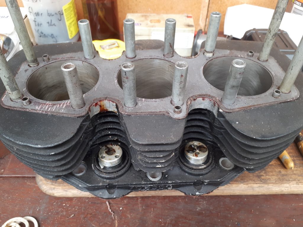
The barrels before clean and blasting. Note the rust in the bores – rendering them in need of replacing.
The plan is to keep my new pistons and replace the cylinder linings. There is a slight cost saving in going down this route but I’m relying on modern materials and machining to leave me with better quality barrels. There will also be some extra meat for grinding away should a catastrophe of some kind befall the Rocket in the future.
I haven’t even shown the head to Ben but I will do so in time. I did produce my shiny new valves that had been removed from the head a few days earlier, only to learn they are of the sub-standard variety and will likely drop down onto a piston after a few thousand kilometres service (oh well, into the bin with those too).
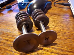
These shiny, new valves aren’t the first choice in BSA triple rebuilds so will likely be passed up in favour of high quality items.
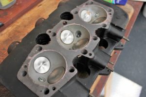
This is what I saw when the head was removed. Clean, new ready to go. Or not.
The plan at the moment is to work our way up from the bottom end, dealing with work in small, bite-size chunks of dollars, rather than a huge bill at the end of the build that would see that not so tiny bit of bile burst forth from my lips.
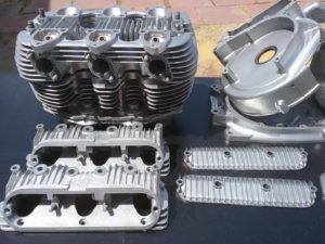
Top end after a clean up.
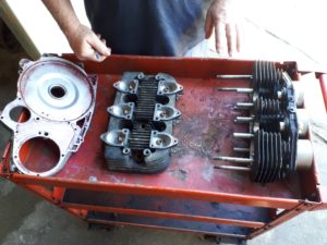
Top end alloy pieces before a clean up. Note the thick black crinkle-paint that was popular in the seventies and eights.
by Dan Talbot | Mar 20, 2019 | Projects
In Part III of the Mustang rebuild we left off with the floor welded into the skeletal remains of our 66 Mustang coupe. I saw this as a major step forward. The body was braced, the floor was in, what could possibly go wrong?
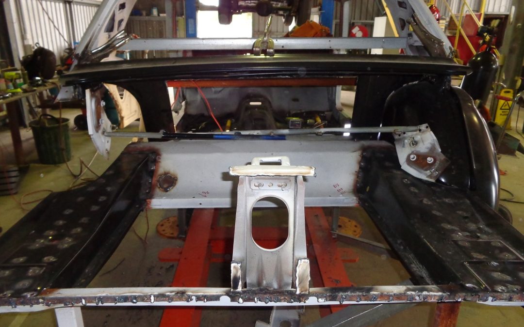
It was time to get cutting. Recall one does not simply cut metal off the body. Each spot weld is removed as a molten glob of metal that is sloughed off the parent metal below without blowing a hole in that second panel. It’s an art that Joe tells me is difficult for about the first 15 years of practice. Suffice to say I blew a few holes in the body panels we intended on keeping. However it’s not the end of the world.
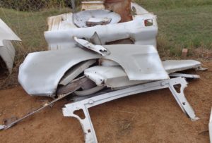
The more we cut, the higher the pile got.
Piece by piece, rusty, crumpled panels were removed from the body and thrown on the scrap heap. Throwing rusty junk metal way was a kind of cathartic experience. I anticipated, with each item that was ditched, a new piece would simply be welded in and, like some automotive phoenix, a rebuilt Mustang would emerge from the ashes. The plan was sound but unfortunately the panels not so much. It’s hard to imagine how after-market panel manufactures could get it so wrong.
Part of the explanation might be found in comparing the panels removed from the car up against the new items going in. I’ve said it before, and I’ll say it again, that this pile of rusty metal and body filler even resembled a Mustang is a remarkable tribute to whomever bashed it back into shape after what must have been some hefty collisions.
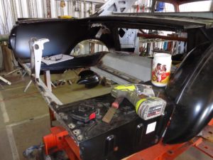
The trusty tek-screw gun came in handy!
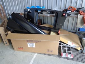
New panels waiting patiently to be fitted to the Mustang skeleton.
As each new panel was loosely fitted to the car my excitement would rise with the anticipation of welding the new item into place but we were a long way from welding. Joe’s trusty tek-screw gun would take the role of the welder, allowing for mock fitting of several parts well ahead of anything quite as permanent as welding.
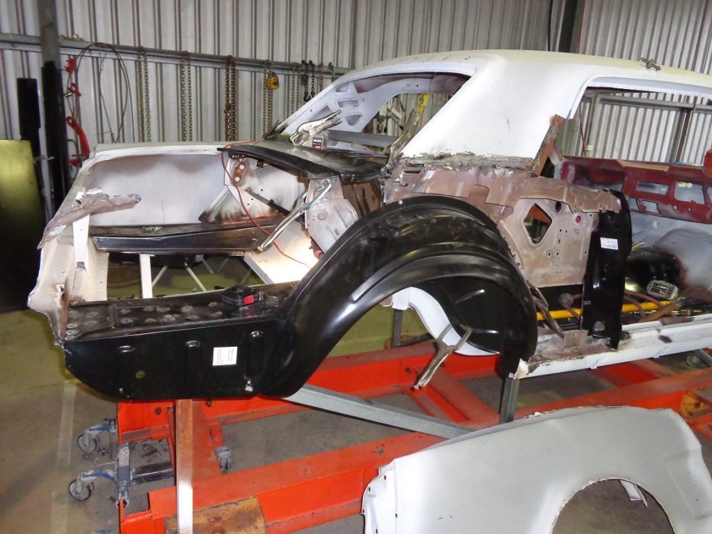
We concentrated our early efforts around the rear of the car. Everything behind the rear passenger’s seat of the car had to be replaced. At one time during the reconstruction the rear-end was practically absent but it was slowly built up by test fitting, cutting, bending and coaxing each panel into place.
One of the major problem arears proved to be the wheel-wells. We ordered two brand new items but they had to be extensively modified before they would fit. I estimate we spent about one and a half days just getting those horrible pieces of metal into place. So bad were they, the shop that provided them actually refunded my money.
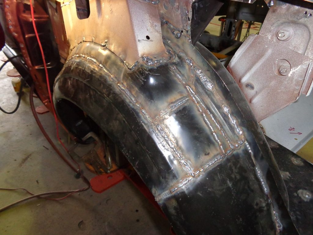
The wheel wells needed significant modification to be enticed into place.
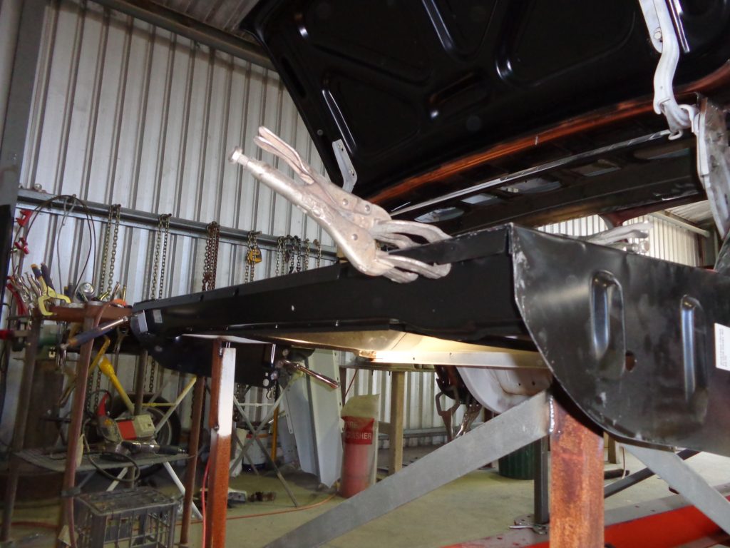
Tek screws and snap-grips came in handy to mock-fit the panels ahead of welding.

by Dan Talbot | Mar 16, 2019 | Collection, Road Tests
Recently we tracked down a stunning example of an Egli Vincent and, for your author, there was a special treat in store.
In Part I of the Egli Trident project, we touched upon the exclusivity of the original Egli Vincent motorcycles and the growing market for replicas and tributes to the brand. Similar to the prevalence of reproduced Norton Featherbed frames, as used on the Motor Shed Triton, Egli frames are being produced by specialist, and some not so special, frame manufactures around the world, such as Colin Taylor who fits firmly into the former group and is building the frame for my Trident. This is just as well because Mr Fritz Egli is no longer producing Vincent-powered motorcycles. Egli has chased the horsepower and has found the Yamaha 1300 engine ideal for his current creations.
Until recently, I had never laid my eyes on an actual Egli Vincent motorcycle, or any Egli machine for that matter so I reached out to John Lagdon, an acquaintance who I knew only through mutual friends. We set up a meeting to allow me to view John’s Egli and spend some time learning more about the Egli setup. In the back of my mind I was secretly hoping John would permit me to sit on the motorcycle to make sure my 6’ 3” body wasn’t too tall for such a bike. My Triton is a bit of a stretch so I’ve been hoping the Egli might be a little more forgiving, although it’s probably moot as by this stage my frame has been paid for, manufactured and electroplated.
Arriving at John’s house, I was met by a tall, lanky man of about the same height and build as me. Instant relief. We walked through the house out to the garage and there it was: the Egli was sitting at the edge of the garage, gleaming in the mottled sun, the big engine hanging bellow a polished aluminium fuel tank, it is indeed a thing of beauty, but it hasn’t always been like this.
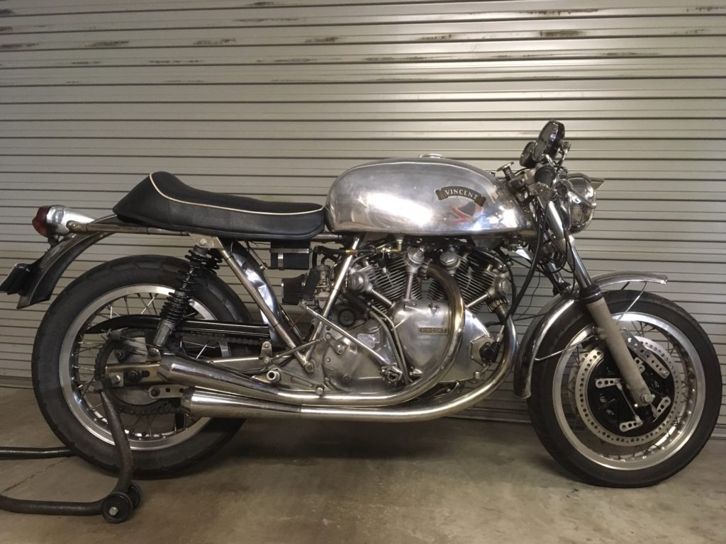
John Lagdn’s Egli Vincent is indeed a thing of beauty. Photograph by John Lagdon.
John found his Vincent in a motorcycle dealership in Cincinnati, Ohio, in around 1985. It was part of a collection of racing machines Domiracer Motorcycles obtained from former racer Ed LaBelle. LaBelle was a three time Canadian road race champion and an accomplished drag racer and it was from the drag racing stock that John secured the beginnings of his project. Evidently the bike was a survivor from the heady days of US/Canadian 1960s drag racing. The engine cases still bear the scars of a drop too much methanol, which I feel add to the history and mystique of the bike, although one can share the heartache of the thrown primary drive chain as it smashed its way out of its enclosure all those years ago.
John discovered the ex Ed LaBelle Vincent drag bike at Domiracer Motorcycles in Cincinnati, Ohio. Photograph by John Lagdon.
It would take a move from the UK to Australia and some 19 years before John got to license his Egli Vincent. There is insufficient space here to go into the trials and tribulations John went through in getting his bike from a project to a functional motorcycle. A lot of the grief suffered by John started even before his frame arrived in Australia. It took an extraordinary long time to complete the frame culminating in John having to, let’s say, get persuasive with the builder. When the frame eventually arrived it was out of true and the nickel plating well below par. A defining feature of an Egli build is a nickel plated frame so I can appreciate his frustrations at something less than perfect. Nevertheless, through determination and perseverance John’s creation was born and the La Belle engine was given a new lease of life on the roads of Perth, Western Australia. Aside from the engine, very little of La Belle’s bike was used in the build, but that’s the thing – there is very little to an Egli Vincent. It’s all engine, a big, stonking, lump of alloy and power that takes that takes centre stage. In a classic case of ‘less is more’ the Egli boasts simplicity and function.
A rare photograph of Ed LaBelle astride his Vincent racer. Photograph supplied by John Lagdon.
Egli motorcycles have a large diameter steel tube that runs from the head-stock to the seat base. The engine hangs from that tube, secured at the top of each head and at the point where the swing-arm pivots, the combine effect being the engine adds to the rigidity of the design in what is termed a ‘stressed member.’ It is simple, functional and highly effective. In another tilt to functionality, the main tube doubles as an oil tank.
The engine on the Trident will sit slightly in front of the swing-arm pivot, secured in place by plates that bolt to both frame and engine. Colin explains, “the Egli-Tri swing-arm is different because of the way it picks-up on plates where, as you rightly say, with the Vincent, it mimics the standard Irving designed location plate which sits between the G1 kicker cover and the drive exit of the engine on the right-hand side of the engine and the boss on the back of the Vinnie’s crankcase. Another one of the significant differences being that the triple’s swing-arm is fabricated from round tubes, where the Eg-Vin ones are made from round pivot tube (mimicking the standard Vin’s design) with flat-sided oval tube legs.” Lesson over, back to John’s bike.
John was happy for me to try the bike out for size and, must have been satisfied I knew my way around a motorcycle because he said “Do you want to take it for a ride?” This is the kind of invitation that rarely comes around and despite not having any protective gear it was not one I was going to decline. As cool as a cucumber I said, “Yeah, sure.” Deep inside I was feeling equal parts happy dance and a gut-churning anxiety. My anxiousness was made worse when John said, “Please don’t drop it.” I hadn’t even thought about that! Crikey, this bloke hardly knows me and he’s letting me loose on his Egli Vincent.
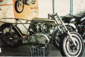
John’s Egli Vincent under construction in Perth, Western Australia. Photograph by John Lagdon.
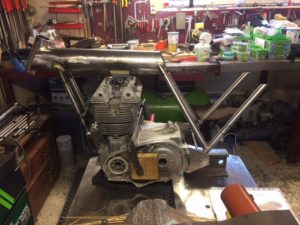
My Egli Trident under construction in Norway. Note the signature 12 cm tube that acts as a backbone on both machines. Fristz Egli’s frame was introduced in 1967 and is still being produced to this day. Photograph by Colin Taylor.
The beast was fired up. Not one for mufflers, John clearly loves the sound of his Vincent. The straight through pipes resemble mufflers, but, don’t be fooled, they don’t muffle a thing. The bark bounced of all the walls in the laneway of what must be a very tolerant neighbourhood.
With a reasonably complicated start-up procedure, the last thing I wanted to do was stall the engine or otherwise let it stop so I idled down the lane blipping the throttle. Enjoying the bark and finding my way around the bike. Once I was satisfied everything was there, brakes, gears, throttle – that sort of thing – I ventured onto the road, and travelled straight across it, oops that turning circle is a bit wide. I paddled the bike backwards and then had another go at riding off.
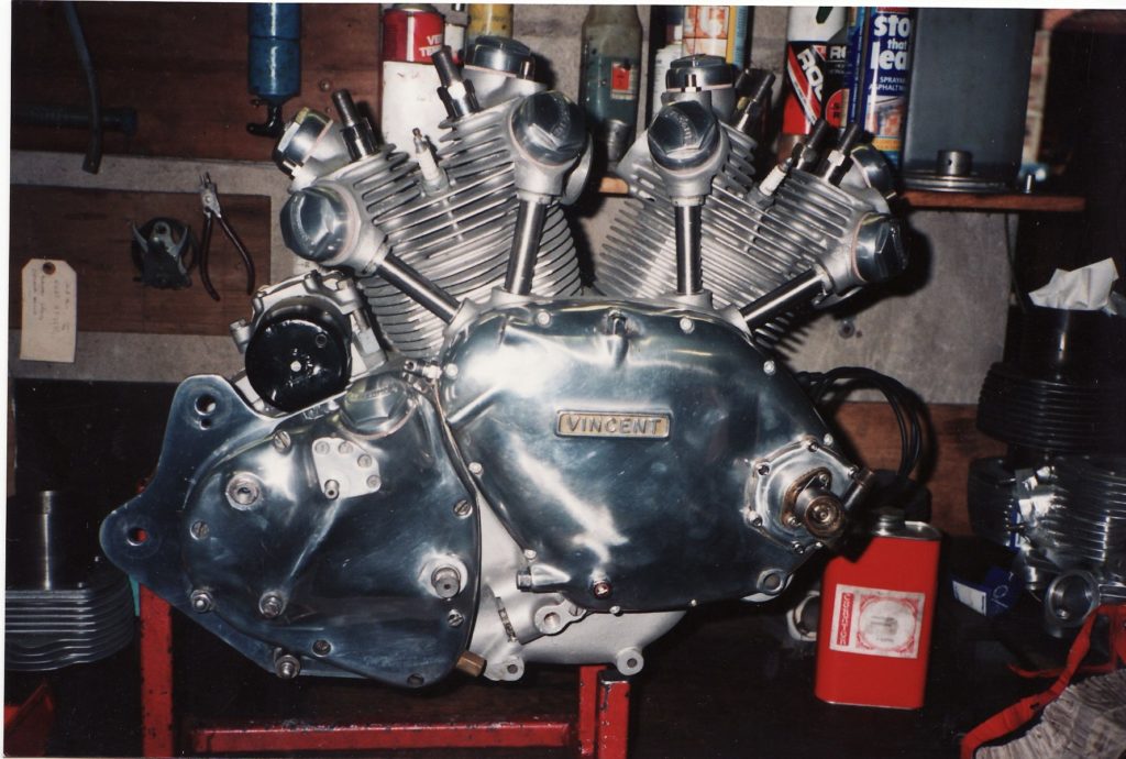
The heart of the beast, the Vincent 50 degree V-Twin engine was the fastest thing money could buy when introduced in 1946. Photograph by John Lagdon.
This time I sort of got going. The gear change, although still on the right side, was directly opposite in movement from my Triumphs so I muffed the first few changes and forward progress was stilted for the first couple intersections until I got the hang of things. Interestingly, Vincents have a gear indicator on the side of the gearbox but I wasn’t about to look down to see what gear I was in, my eyes were planted firmly on the road ahead.
Some say Vincent engines only fire at every second lamp-post but this thing hammered. In the few brief opportunities I had to let the Vincent off the leash I got it, I understood the magic. It pulled hard and gave me a glimpse into the world of the Vincent. I would have loved to explore the upper limits of the engine but not as long as it belongs to someone else, additionally suburbia intervened and I was frequently calling on the massive front, 8 leading shoe arrangement to slow the beast. The rear brake had been lifted from a BSA and was the same as the one on my Triton so I was aware that was pretty useless. But, I’m happy to report, didn’t crash or drop the bike.
Idling back into John’s laneway I felt relief at having successfully navigated a few suburban streets on the most valuable motorcycle I had ever ridden. The bike was comfortable enough and nimble beyond the bulky appearance, sufficient to let me know I had made a good choice in opting for an Egli setup for the Trident. It was also sufficient to let me know I must one day build an Egli Vincent.
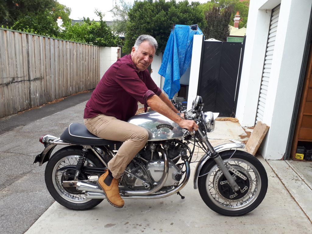
The author about to experience a special treat – my first ride on an Egli Vincent.
by Dan Talbot | Mar 14, 2019 | Events
Hold the press, the Motor Shed Thunderbird picked up outright winner at this years Indian Harley Club 2 Day Rally. Billed as “WA’s Premier Historic Motorcycle Event” we beat about 170 other machines to victory and picked up a nice tool-kit as first prize.
Day 1 dawned a sodding-wet Saturday but, aside from getting the bike very grubby, things weren’t too bad. By Lunch time it had stopped raining and we enjoyed a nice ride through the forests of the South West of Western Australia. Some of the towns visited included, Donnybrook, Kirup, Nannup and Balingup. I reckon we won because the old British bike was in her element.

Never mind the rain tumbling down, the Thunderbird is pushed off the stand and we’re ready to go.
A sodding wet autumn day in the South West of Western Australia.
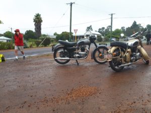
Morning tea break and, you guessed it, still raining.
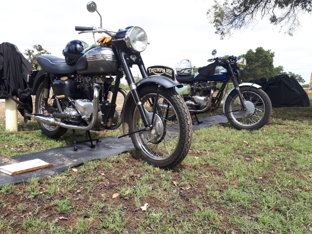
All finished. The end of day two and the Thunderbird is parked up alongside a sister, pre-unit Bonneville.
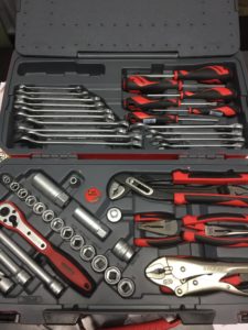
Winners are grinners! A lovely new tool kit as first prize.
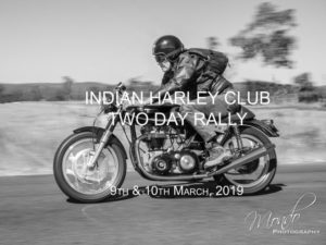
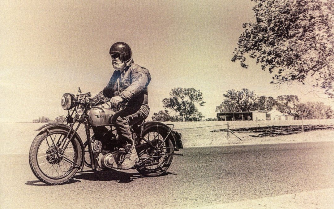
The original promotional material for the Two Day Rally featured the Motor Shed Triton but some deemed it a bit to racy and it was bumped in favour of the BSA pictured below.

by Dan Talbot | Feb 23, 2019 | Collection, Projects
Taking up from where we put the torch down, the Mustang had panel after panel peeled off until it has hardly recognisable. The floor was the first to go with the new single piece, front and rear, going in.
A ‘new’ floor is exactly that. Pressed from a single sheet of metal in Thailand, Mexico or Canada, most of the panels that went into the Mustang were manufactured by Dynacorn. It is actually possible to purchase a whole body from Dynacorn. Sadly, that won’t work in Australia as, apart from needing a fat cheque-book, any car built using a new body would have to pass as a current model with all the emission restrictions and safety requirements that would bring before it could be registered, unless, of course, you had a sacrificial chassis number with import approval etc. I’m sure that happens, but not in my case, my car is a piece of Aussie motoring history and I needed to retain as much of it as possible.
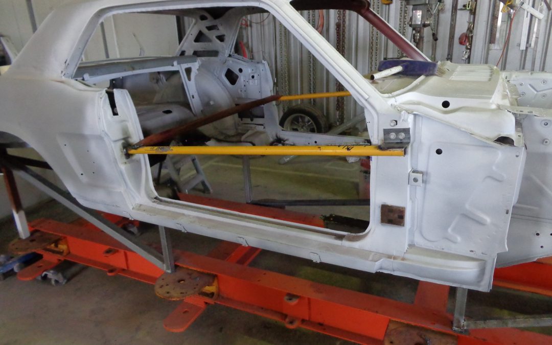
To remove the floor large portions of metal had to be cut out and tossed on the scrap heap. With the large portions removed the spot-welds can be accessed and burnt off without destroying (too much of) the metal beneath: that is, the portion we want to keep. Spot welds can be drilled out but on something as large as the floor there are dozens of the bloody things so drilling would have been labour intensive, nope, better just to blow it away.
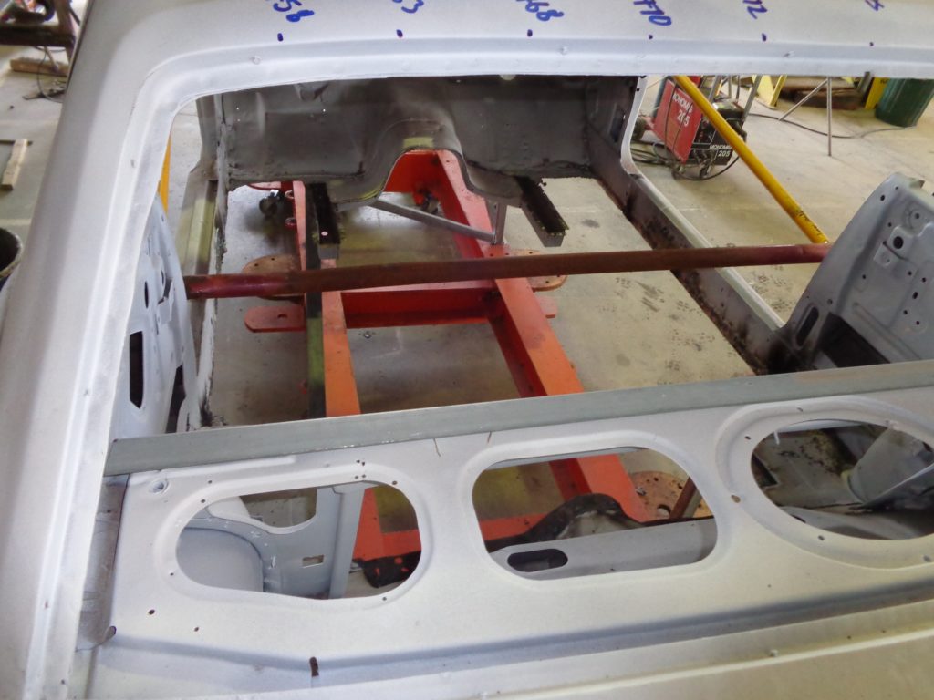
That’s a major portion of the car missing right there. Note the bracing. Without this the car would probably have collapsed.
With the metal all cleaned up, it was time to fit the new floor. Recall the body is securely braced so she won’t suffer any structural movement between the old floor being cut off and the new one going in. Further to this, we had thoroughly measured the whole body, back to front, up and down, inside and out, and recorded the measurements in both a book and on the metal.
With the floor roughly in place, it was time to pummel it with tek-screws. Joe kept belting them through my precious-metal like there was no tomorrow, the underside of the car looked like a bloody porcupine! I would later come to love the simplicity of holding everything in place with the humble tek-screw, a marvellous invention.
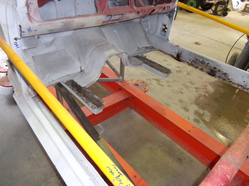
We’re jumping ahead here but those two stubby chassis rails would later be connected to the rear pair, with two pieces of metal pressed for the purpose, adding immensely to the torsional rigidity of the body. Something Ford should have done when they built the car.
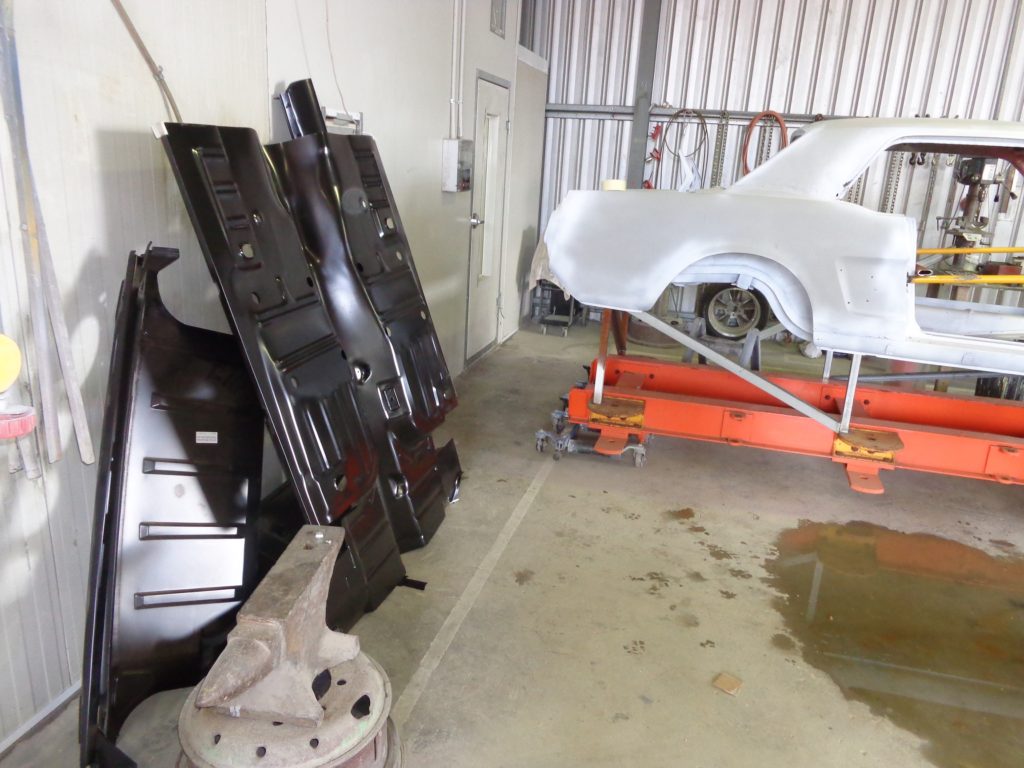
The brand new floor waiting to go in.
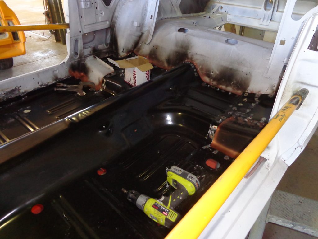
The new floor went in quite easily, tricking me into thinking all the new panels would similarly go together.
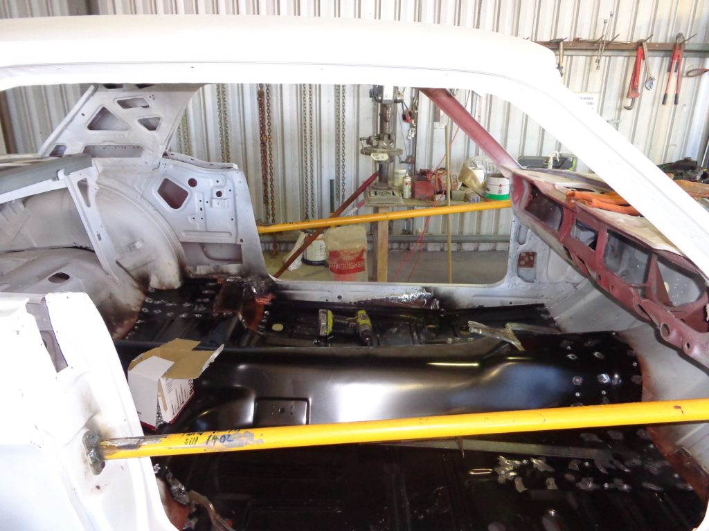
The new floor is held in place by tek-screws ahead of welding.
Conveniently, there was another, recently painted 1965 Mustang in Joe’s workshop waiting to be refitted. It was in a separate shed and many was the time I traipsed across to the other shed, tape measure and notebook in hand, to measure and record the dimensions of the ‘65 couple, which is essentially the same body as my ‘66.
I used to look at the finished ’65 and marvel at the lush silver paintwork dreaming of the day mine would look that good again. In time it would, but we had a lot of work ahead of us.
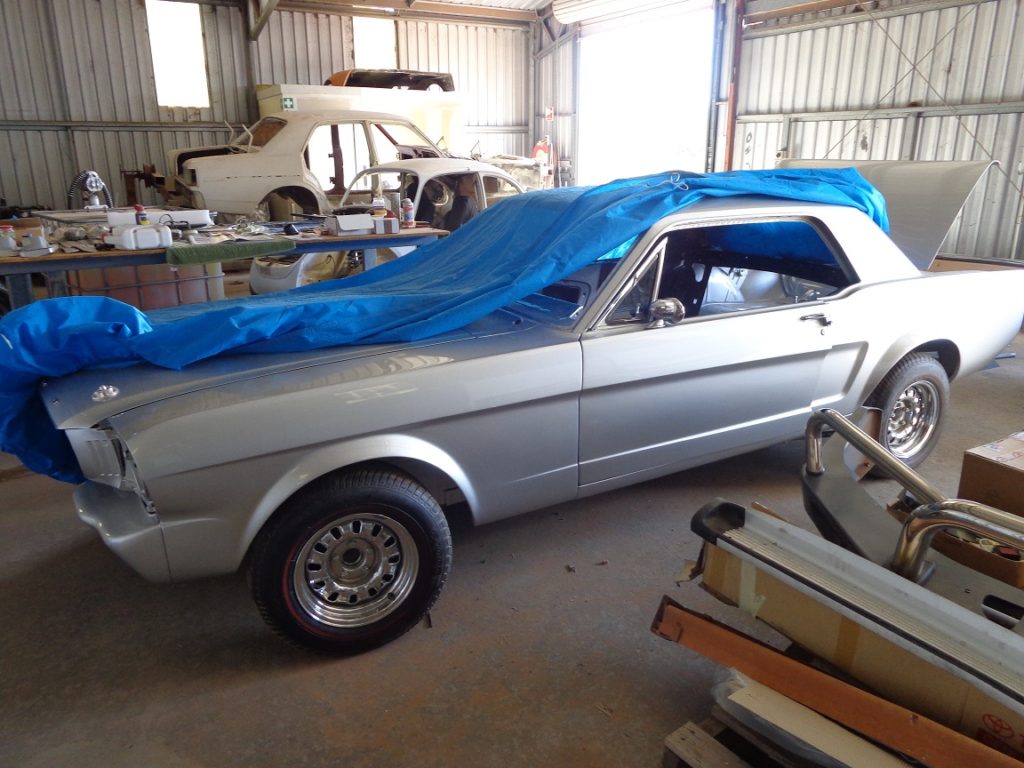
Always have access to another car for reference purposes.
What we’ve learnt
- Said before and repeated here, brace the car!
- Measure, remeasure and measure again.
- One cannot make too many recordings of the body dimensions.
- Tek-screws are your friend.
- Finally, have another, intact, car nearby for reference purposes.


