Rocket Three Restoration: Part IV
Wow, how time flies. The last time I wrote an update on the Rocket 3 project was almost 12 months ago. In my defense, I have been busy with another big writing project which is done so now it’s back to the Shed.
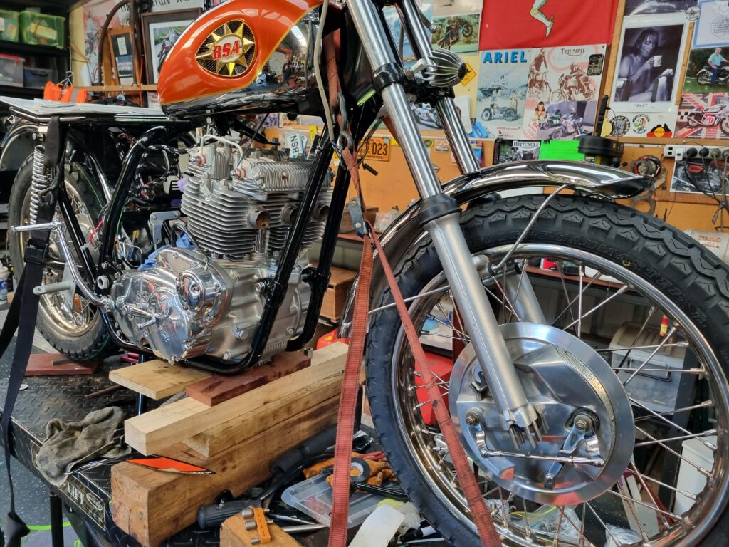
Since I last wrote about the Rocket there has been quite a bit of progress, most notably the engine is finished and back in the frame. The engine, if I may say so, looks absolutely splendid but I can’t take the credit for it’s rebuild. Some months ago, I boxed up all the parts and delivered them to British Imports in the Perth suburb of Malaga. I have no doubt that I would have been fine assembling the engine but there are so many tales of these old triples flying to pieces when not done right. Added to this, recall last time we discussed the Rocket I expressed an idea I may perhaps keep the bike instead of selling it. I tend to be a little harsh on machinery so I didn’t want to leave anything to chance and I would hate to have to remove it again.
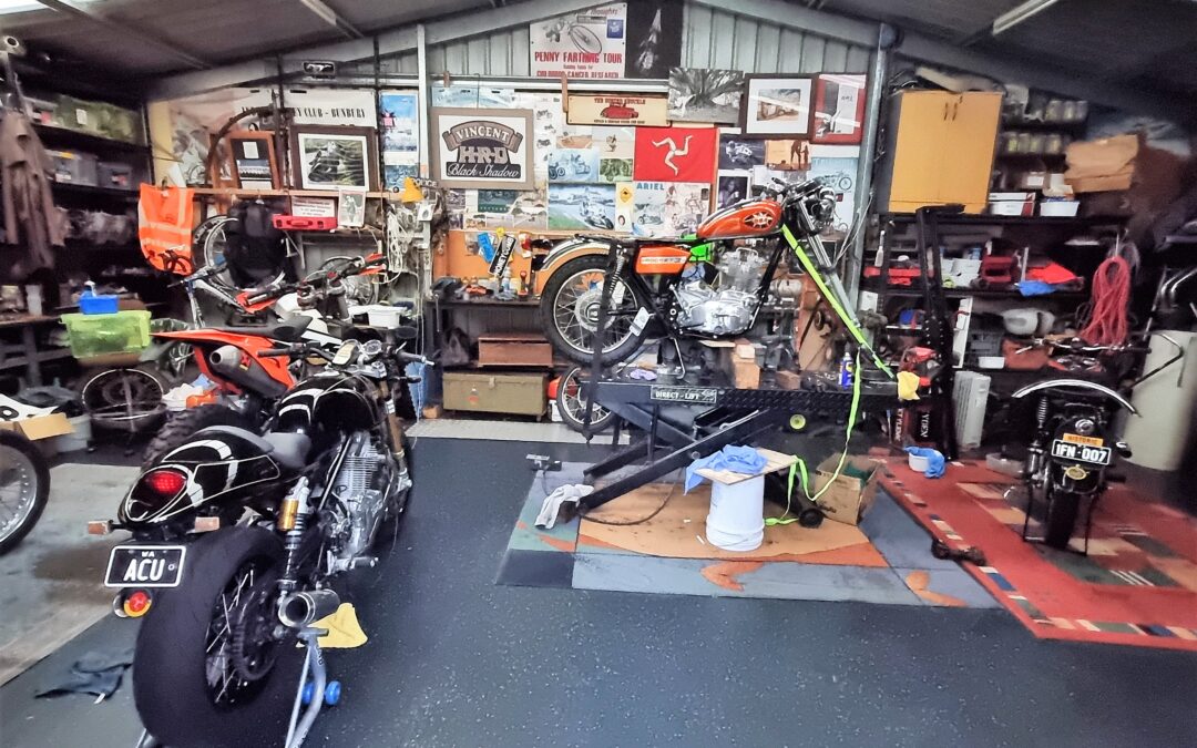
One thing about these engines is their incredible weight. I believe it is somewhere around 125kg. This means, if you don’t want to risk scratching the frame or breaking fins of the engine, at least three people are needed to get the engine back into the frame. It’s a tricky job but we got there. This was also the first time the engine had been introduced to the frame so it was somewhat of a blind-date. The big test in how this two were going to get on was the engine mounting bolts. I’m happy to report, with some gentle persuasion the mounting bolts were settled into place and the engine and frame are living happily together.
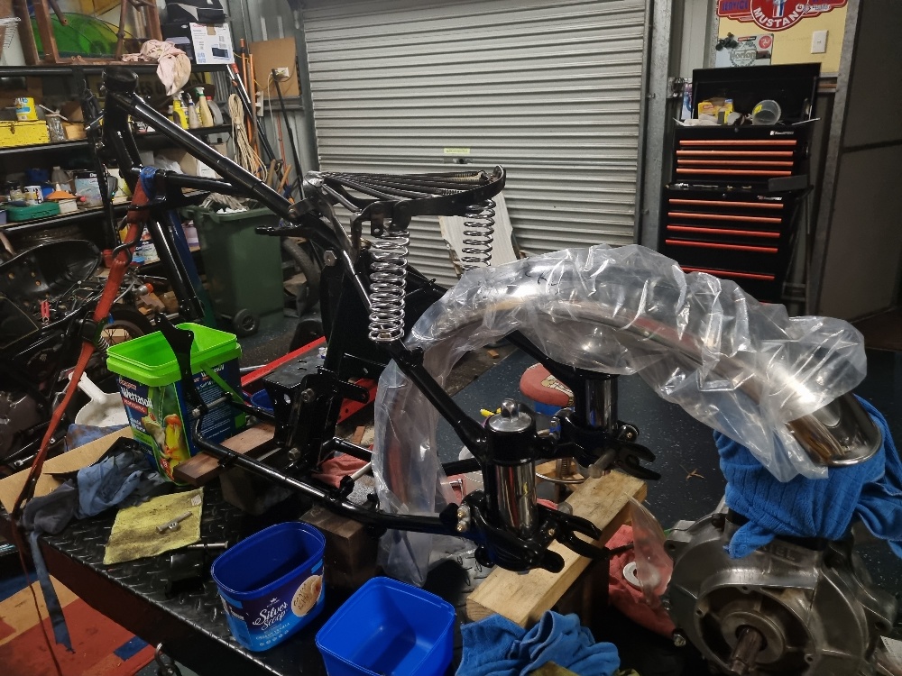
The 125 kg engine is, at last, nestled in the frame.
Once the engine is loosely back in the bike it must be shimmed to ensure it is in the best possible position for the chain to line up between the gearbox drive sprocket and the rear wheel sprocket. I did have shims but they were not going to line-up so I went off and purchased some 20mm stainless bar and went off to see Dave my machinist friend who turned out half a dozen shims. Another friend had sent me instructions on how to shim a BSA/Triumph triple engine which helped a lot. Essentially, there is a point at the bottom of the frame where the engine mates to lug and all other shimming must follow. After two more visits to Dave, I had the engine snug against all mounting points.
Three shims were required on the left side of the engine. All of them had to be custom made as we’re inserting a 1971 engine into a 1969 frame.
Shims at the front of the engine. Clearly, the engine is offset but I am assured this is how it should look.
The next job was fitting the wheels. I purposely left them off in case I had to approach the installation by sitting the engine on its side and lowering the frame over it. During some experimentation involving the rear brake spring, I accidently broke the alloy brake plate, necessitating a trip to a welder who was good with alloy for a repair. The hub was then sent to Perth to be refinished. Similarly, the front end could have gone more smoothly but I complicated things.
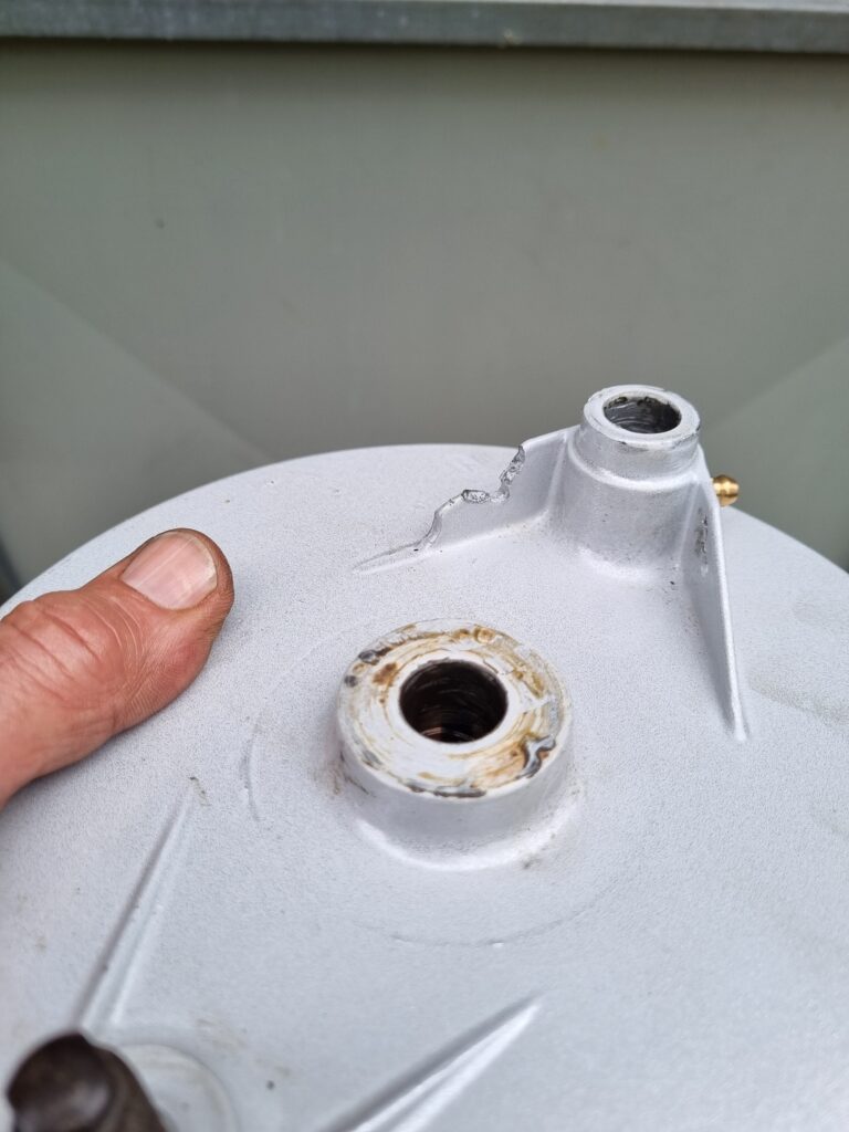
Evidently I was too heavy-handed in trying to fit a recalcitrant spring to this alloy hub. Never mind, it gave be an excuse to strip that awful powder-coating from this brake backing plate.
Now to find someone who can weld alloy.
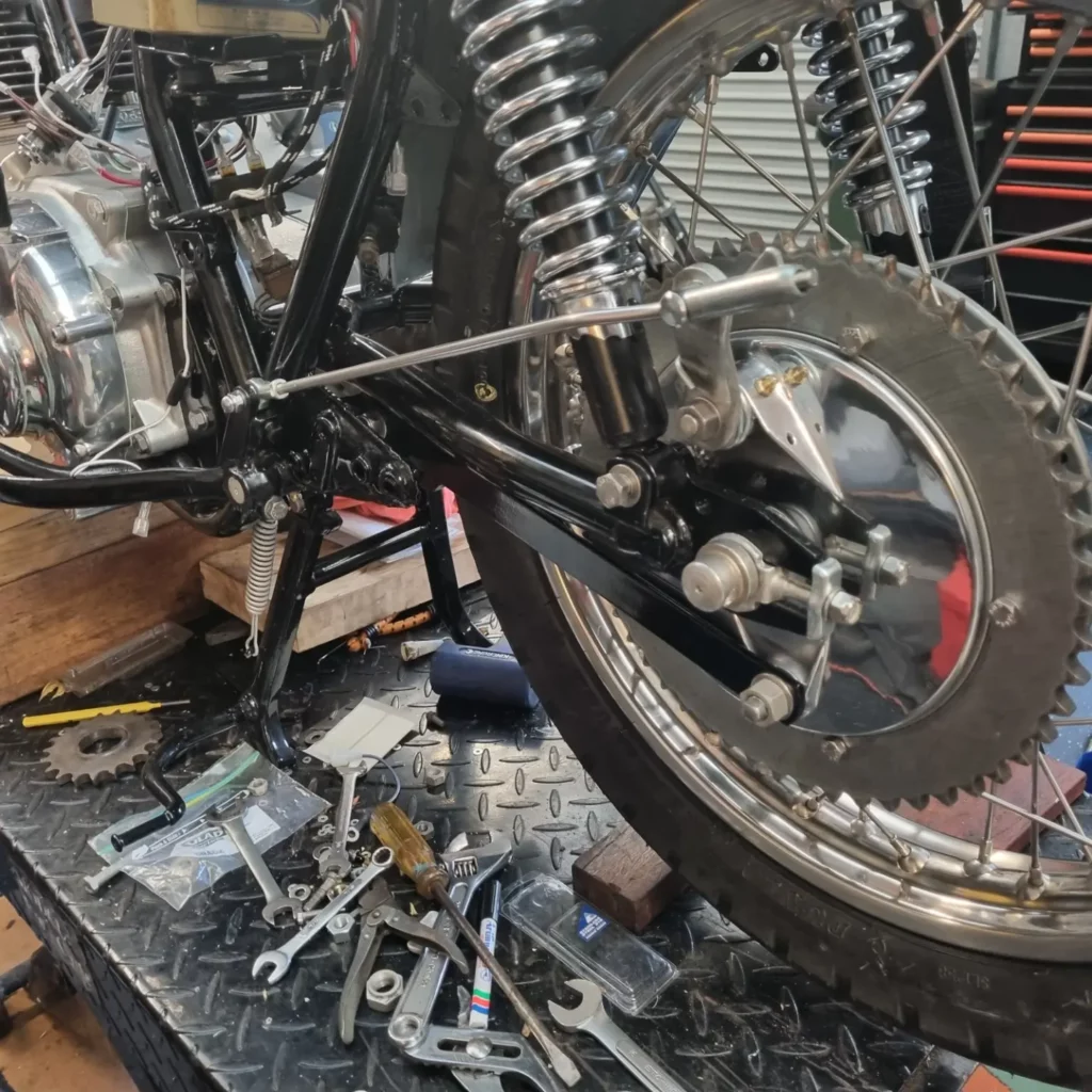
The brake backing plate is repaired and in situ.
When BSA restyled the Rocket, for reasons known only to the designers, they fitted a sub-standard brake hub to the front wheel. The result was the earlier Rocket 3 had a superior front brake. I have obtained such a hub with the intention of fitting it to my Thunderbird. I experimented with putting it on the Rocket but it was never going to work – refer to the pictures for more of an explanation. With each change of the wheel, I had to swap the tyre over. It’s been on and off three times now so I will remain with the standard brake for now but I have been collecting bits and pieces to fit disc brakes to the machine so we will see what eventuates.
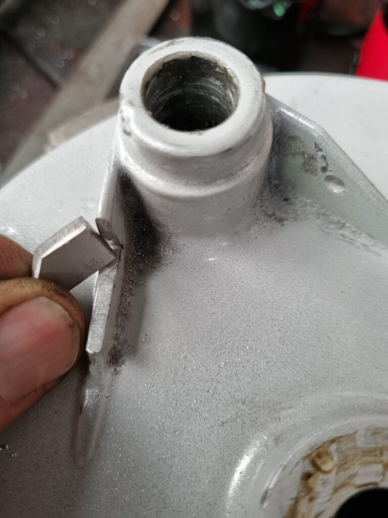
My experiment in fitting this more effective brake hub didn’t work. It is designed for use with steel fork legs. These later alloy items fouled the mounting point resulting in the air scoop pointing too high.
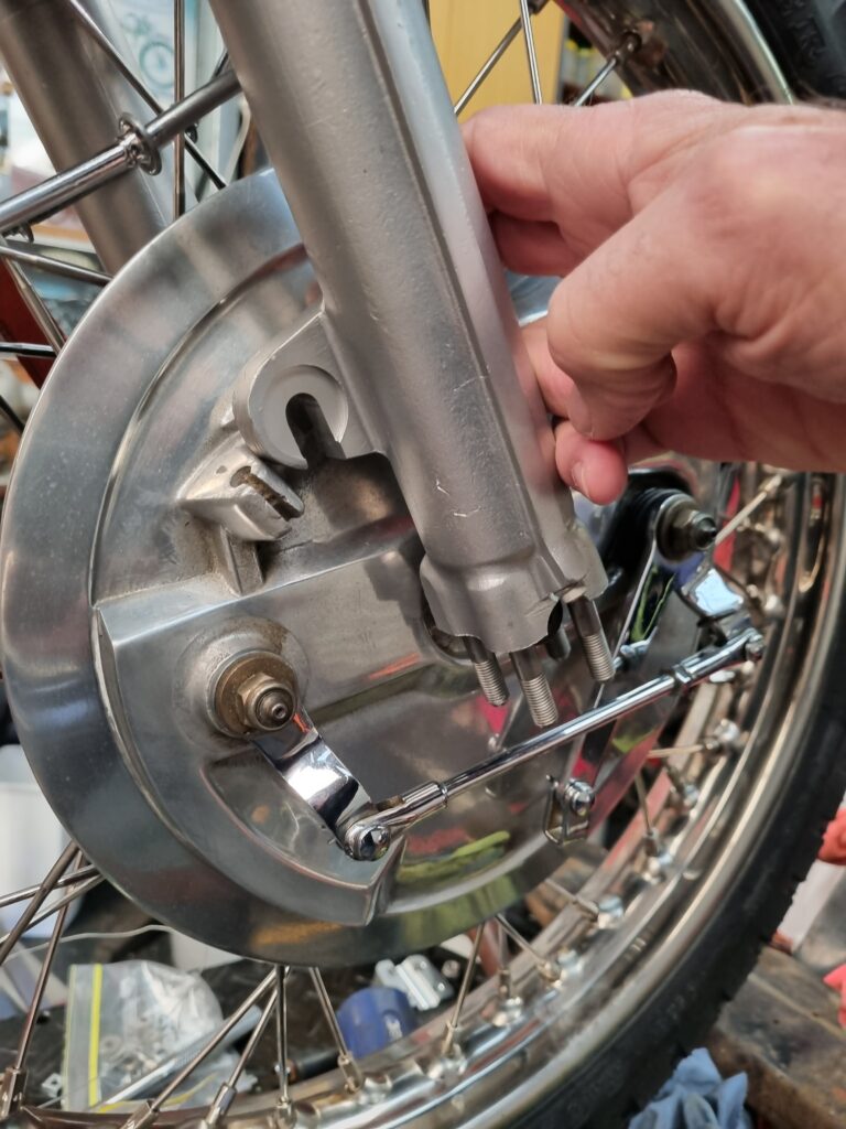
This is where the problem lay.
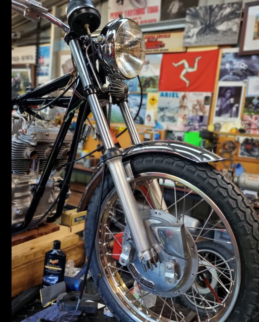
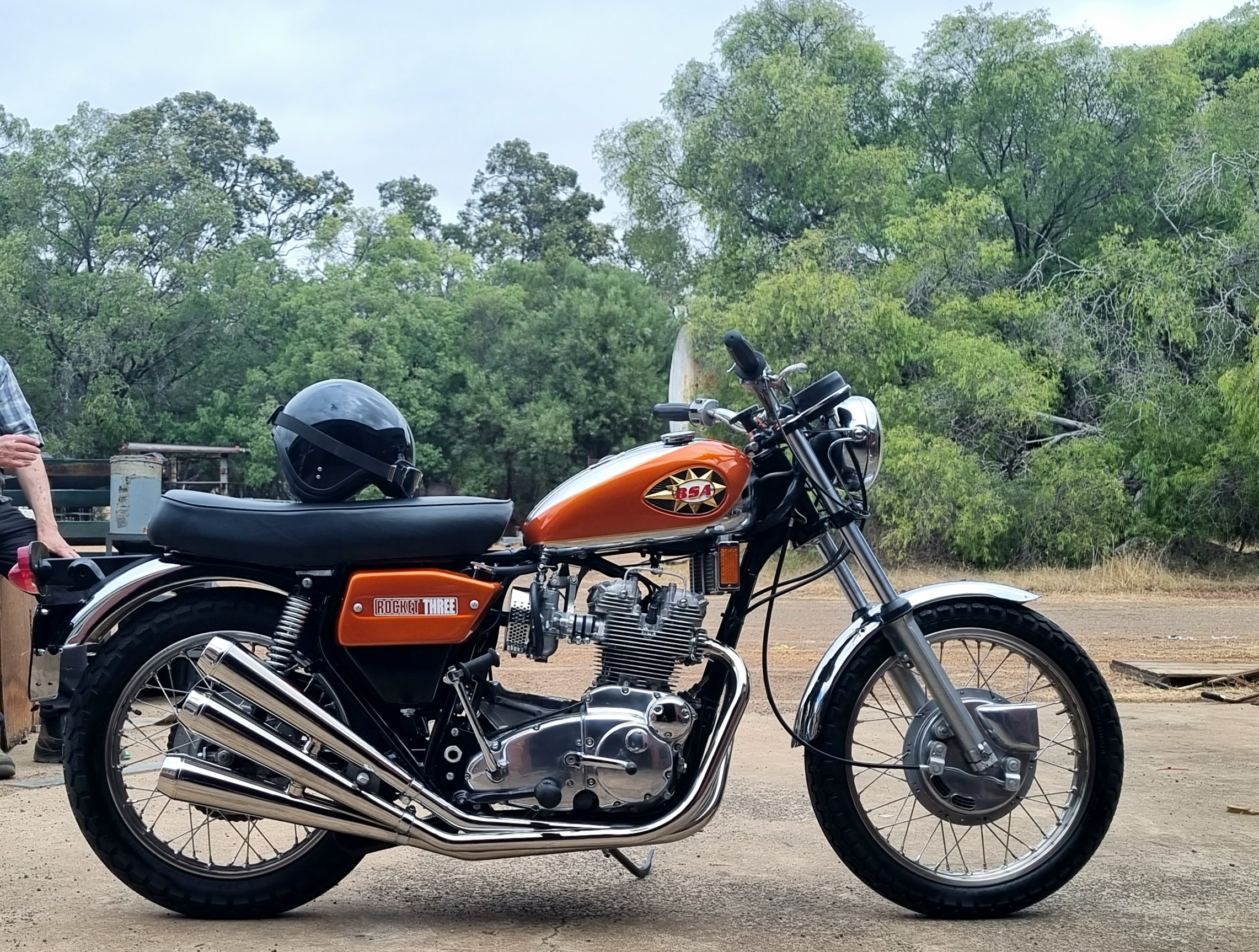
Here the bike sits with the conical brake fitted. Due to its ineffectiveness, the conical brake is often referred to as comical.